 |
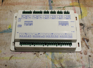
| The RDC6442G controller from Ruida |
This is going to be quite an image heavy post describing the rewiring needed to convert between the Leetro controller and the Ruida controller. It is also pretty straight forward on the old Just Add Sharks laser cutters because all of the wires are clearly labelled. The controller was prepared in the
previous step in order to make this conversion process as smooth as possible.
 |
| The Leetro (Pad03) panel on the left and the Ruida panel on the right |
 |
| The view from inside the laser looking up at the control panel |
The control panel is an easy place to start, both panels have just a single cable that runs down to the controller, both panels are a very similar size, with the Ruida panel being slightly smaller underneath so it will fit in the hole left behind easily. The Pad03 panel clips into place so you'll need to reach up inside the machine to work the clips loose. The cable runs down the inside of the laser and is cable tied onto mounting points inside the metal work.
 |
| The bundle of wiring loom cable tied into place |
There tends to be a lot of excess wiring on these machines, a 2m long wire will service 10 different models of laser so the long wires tend to get doubled back on themselves and cable tied into a bundle. Before cutting your cables loose consider wrapping them loosely with a new cable tie. This will keep the bundle in some semblance of order and once the new cable has been passed through the bundle it will be very easy to tighten all the ties quickly.
 |
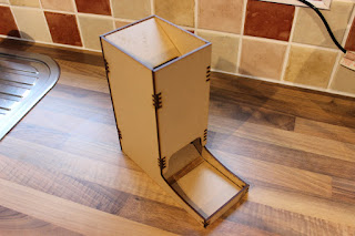
| The Ruida panel in it's new home on top of the laser |
 |
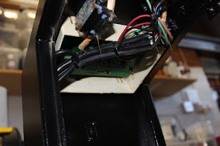
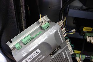
| The Leetro controller in place next to the stepper drivers |
In my machine, the Leetro controller is mounted vertically in the side of the cabinet, I'm able to use the same mounting holes to hold the Ruida controller in place. They're a little wide but the Ruida can rest on the bottom screws and the top screws stop it from falling forward.
 |
| The laser connection on the Leetro controller |
 |
| The laser connection on the Ruida controller |
The first connector I rewired was the laser control connector. It's a simple 3 wires and all are clearly labelled.
- GND from the Leetro becomes GND on the Ruida, this is the base voltage level for the electronics.
- LAS becomes L-On1 on the Ruida, this turns the actual laser beam on/off
- DA becomes LPWM1, this is the amount of power to use for the laser beam as a PWM signal.
- WP1 is the water protection input, I have temporarily left this unconnected
- L-AN1 is the analogue output to control the power of the laser beam, see below
There are two options for setting the power of the laser beam. PWM which is a modulated square wave and potentially more precise and an analogue signal where the voltage varies between 0 and 5V. I have chosen the
PWM pin from the Ruida, a while back I upgraded my High Voltage Power supply to something that works better with a PWM input. The standard power supply on these machines should be able to accept either input.
The Ruida controller has the option to drive two different laser beams, CN6 is an identical connector that would connect to a second high voltage power supply.
 |
| X & Y stepper motor connectors on the Leetro |
 |
| X,Y & Z connectors on the Ruida Controller |
The next set of connectors that's easy to convert are the X,Y and Z stepper motor connectors. A stepper motor requires two digital inputs, the first tells the motor which direction to turn and the second instructs to motor to move a single step.
- DC5V from the Leetro becomes +5V on the Ruida, this is the upper voltage level for the signal.
- PULX/Y/Z becomes PUL on the corresponding X/Y/Z connector
- DIRX/Y/Z becomes DIR on the corresponding X/Y/Z connector
With the X,Y and Z connectors switched over it would be possible to drive the axis on the laser but it's best to add in the limit switches for the next step. These need a little bit of rerouting to connect to the new controller. When remaking the wires it's useful to have a
wire end crimp tool, this allows you to put ferrules back on the wires, keeping it looking professional.
 |
| The Leetro controller has 3 wires for limit switches but most aren't used anway |
The leetro controller only really uses two wires for each axis, one goes to the limit switch and one returns from it. It doesn't really matter which way round these two go but they are consistently coloured with blue as GND. There are several other wires but these are technically redundant for both setups.
 |
| The Leetro controller has the Z+ limit and the Z Origin connected to the same switch |
 |
| The Ruida controller doesn't have the Z Origin so only the Z+ limit is connected |
On the Z axis the green wire for ELZ+ was removed and the label switched to the remaining brown wire.
- GND from the Leetro becomes GND on the Ruida, this is the base voltage level for the electronics.
- ELZ+ becomes LmtZ+, this signifies when the Z axis has reached it's limit switch
 |
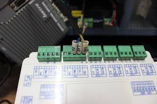
| A common GND signal for both the X and the Y axis |
The X and the Y axis follow a similar convention, all of the extraneous wires were removed. CN4 on the Ruida only has one GND connection though so the GND wires for both the X and Y were routed into this pin with a new ferrule connector.
- GND from the Leetro becomes GND on the Ruida, this is the base voltage level for the electronics.
- ELX- becomes LmtX-, and relates to the min X position and origin point.
- ELY- becomes LmtY-, and relates to the min Y position and origin point.
That is all of the wiring required to make the laser cutter functional again. I powered up the laser cutter in stages, deliberately leaving the laser power connector disconnected until I was sure that the XY and Z axis were functioning properly and moving the right amounts. In the next post I'll talk through that process and some of the minor kinks I discovered along the way.