Posts

Showing posts with the label Tutorial

Making a Move

Image
We have buttons and LED's available to the system so it's probably time to introduce some element of movement. One of the cheapest and easiest ways to do this is with a servo, typically a small geared electric motor with it's own built in control circuitry. A single digital control line commands the servo to drive to a specific angle and the servo monitors it's own position as it attempts to move to that angle as quickly as possible. Servos are very versatile devices, you can get some basic 9g servos for only a few pounds each. Servos come in a range of standard rectangular sizes so they're easy to draw and have mounting points built into the plastic shells. If you require stronger/faster movement you can often buy a more expensive servo that fits into the same space and is controlled in exactly the same way so switching them over is incredibly easy. Most servos are controlled through a standard three wire connection, two wires for power and GND, the third wire car...
Switching Game Modes

Image
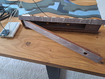
Having produced the knife switch housing and wiring it into the system I can now use it to form the basis of one of the games in the final puzzle box. It may be simple but this is the first of the puzzles/games that players find. The puzzle requires the player to take the radiator key  from the inside of the box, find and undo the screw, left the panel and flip the knife switch to the 'on' position.   The main purpose of this game is to subconsciously show the player that the box is now empty, once they have removed the radiator key from inside it. It also doubles as a handy on/off switch for the game. I could have hardwired the power to go through this switch but there are better things that can be done. If the power comes on at the start of the game then we can time how long it takes the player to solve the whole game. The other neat thing is one of my design philosophies for this box. I wanted this whole game to have as little reset required as possible. If the up positi...

Binary Puzzle

Image
I said we'd take a little detour to make a fully functional puzzle using our two buttons and two lights and so I present to you, a Binary Puzzle. I have made two binary style puzzles before, one was purely mechanical , and the other one used a cabinet lock and a series of switches to activate it (but no blog post). Both of these are simpler ways of making the same puzzle so we need this to be different somehow. Since we have the full power of a microcontroller why not make the codes change over time. Every time you fail to enter the code correctly it will change the code, so let's dig into the system. Hardware wise it's a bit ugly, all of the information required to solve the puzzle is contained on the front of the panel which could be mounted in a box or in a wall. The reverse is just enough hardware to hold everything in place and some basic soldering to recreate everything on the previous prototype board. Two switches connected to D5 and D6  using the internal pull up...

How to Fade an LED

Image
In this tutorial we're going to talk about fading an LED from On to Off and back again but I think it would be really useful to have two LED's to fade. This means a short detour into setting up LED's and most importantly current limiting resistors. Most modern microcontrollers are capable of supplying enough power to directly drive an LED, meaning you can connect an LED to an IO pin and directly turn it On/Off. There is a limit to how much power the pin can supply and also how much power the LED can take before one or the other will burn out. You should never connect an LED directly to a power source, you should always have a resistor in line with it to limit the maximum amount of current that can flow through it. To calculate the exact amount of current flowing through a circuit you need to know Ohms law .  Voltage = Current x Resistance .  We're using a 100 Ohm resistors in this circuit, so if it were connected to 3.3V output on the GPIO pin the current would be 3.3/...

Multiple Buttons and LEDs

Image
Yesterday's post showed the making of this little two button remote control  so it seems only right to to include it in this post about reading multiple buttons. It's just two simple buttons that pull the data line down to ground when pressed and could easily be recreated on the breadboard if required. We're also going to talk about multiple LED's and set up the framework for using multiples even though the we're only going to using the one built in LED again. The main difference between this program and the previous one is that the inputs and outputs are going to be defined as arrays of values instead of just single values. Right at the top of the program it's important to define how many inputs and LED's there around going to be and then create an array of values to declare which data lines these things are going to be on, in this instance D1 and D2 and the same LED as before. even though there is only one LED we can still define it in an array. Now when...

How to Read a Switch

Image
So far we've covered how to blink an LED on and off and how to flicker an LED using an analogue output value, it's time to start reading and reacting to inputs to the controller. This means adding some additional hardware to read from, but today that can be a simple as a single wire on a prototyping breadboard. One end of the wire is connected to the D1 input and the other end is swapped between the 3V3 pin and the GND pin to create High/Low input signals. The initial code to read this is impressively simple, we're also going to leave some LED code in the demo so that we can easily see what value is being read by the controller. When you load this example you should see that the LED turns on when the wire is connected to GND (remember the LED_BUILTIN is active low) and the LED turns off when the wire is connected to 3V3. This system works but has a downside, the input pin only changes state when the wire is connected to the new pin. When the wire is disconnected and l...

How to Flicker an LED

Image
In the last tutorial we covered how not to blink an LED , where I explained what was wrong with the most common blink example and showed a much more elegant solution. We now have an LED that switches between 'Off' and 'Blindingly Bright', there has to be another way that gives us more control over the LED, reduces the brightness (and therefore power consumption) and that could also give us a bit more 'character' for our lights. The answer is Pulse Width Modulation , or PWM for short. By switching the LED power on and off, imperceptibly quickly we can control the average amount of Voltage that is supplied to the LED, which in turn reduces the current and brightness of the LED. If we switch the power on and off faster than the LED can react, the LED will receive an average Voltage that is proportional to the ratio between on and off. If the LED is on for half the time and off for half the time it will receive half of the full voltage. It is possible to create the...

How not to Blink an LED

Image
It is my intention to cover the whole depth of the coding that went into the NikolAI puzzle box  and I really didn't want to start with the 'Blink LED' project because everybody does that and it's been done a million times over but it's just too darn useful. I'm not going to cover setting up Arduino because even I've done that tutorial before. PinMode(2, OUTPUT); set up digital line 2 as an output to turn the LED on/off DigitalWrite(2, HIGH/LOW); actually turns the digital line 2 on/off, blinking an LED Delay(1000); creates a time delay of 1000 milliseconds between turning the line on/off So there it is, the simplest blink LED program. This can be found all over the internet and it does the job of blinking an LED and that's about it. There's actually a few issues with this as a program and you'd never use it in sensible program so I thought it would actually be much more useful for me to describe what's wrong with this example and lay ...

Rust in Pieces

Image
With my recent builds for EMF camp I had an opportunity to try some new weathering techniques. My skills are a bit lacking and there is lots of conflicting advice/techniques online and my time was short so I went straight to Eldritch  and Simon gave me some definitive answers on the subject of rust. I thought I'd write the info down here so that it can hopefully benefit someone else. You will need. White vinegar and salt, available from any supermarket and you probably already have them Hydrogen Peroxide , available online or I got mine from the Boots chemist. They were unsure they even stocked it so it may pay to be a bit persistent and ask them to actually check the drawers. You'll be asked why you want it but when you have a legitimate reason like this the conversations are always fun. Iron Powder , this is pre rust and not the same as Iron Oxide Powder (post rust). I bought 500g on ebay and now have about 450g left over.  Super glue, I opted for ...

Firmware Reset

Image
During the wifi configuration tutorial I described a method to provide a firmware reset in the case that you forget the user name and password using an additional button (or wire loop). I also lamented the problems of the Wemos D1 board not being able to distinguish between a power cycle and a button reset. Today I'm going to discuss another way to achieve a firmware reset of the device without the requirement for any additional hardware. The method itself is quite simple and we have already used all required parts for the wifi configuration program. The first thing the device should do when it starts up, is set a flag in the non volatile memory and after a given period of time it should clear this flag again. Now if the device is reset before it has the chance to clear the flag we can tell that the reset button has been pushed twice in quick succession and use that as an indicator that we want to perform a firmware reset. There are a few items to declare at the start of ...

ESP8266 Wifi Configuration Part 2

Image
In Part 1 of the Wifi configuration tutorial  we learned how to set up the device to read/write from non volatile areas of memory so that we can recall a new wifi ssid and password between reboots. In Part 2 we're going to provide an interface that allows you to set the new values from a web page. This tutorial is a combination of all the previous parts so I'll include links to the relevant parts rather than run through it all again. The one part we missed from the last tutorial was actually creating a wifi network. We need to include the ESP8266Wifi library and open up a new access point.  Do this after loading the new wifi values to ensure the network has the correct name. The next step is to set up a webserver to provide pages to the user. We're going to create a default index page that's just simple text. For the tutorial this will serve to point the user in the right direction for the admin functions but in a full program this would be whichever page you ...

ESP8266 Wifi Configuration Part 1

Image
So far with the ESP8266 modules we've been using the same network name and password, these values have been hard coded into the program for ease of use. Now imagine that we had a dozen devices all running at the same time, all trying to set up the same wifi network (and yes I realise by using the mac address as part of our SSID we have avoided this problem). The solution, that we're going to talk about today, is to allow the user to configure the network name and password. This is simply good practice as anyone who has logged into a device using 'admin' and 'password' should realise. The first step is to find a way to store the new values in a way that they will be remembered while the device is turned off, and then be able to load that information when the device turns back on again. On a standard Arduino we'd use the EEPROM which would allow us to write data to a specific type of memory that requires special electrical conditions to be programm...

The DNS Dilemma

Image
DNS is essentially a naming system for computers and services connected to a network. It's a way of mapping an IP address to a name and keeping that connection even if the IP Address Changes. You could visit google by going to http://172.217.0.0/  but it's much easier to remember and type http://google.com/ into your browser instead. So far we've been accessing our ESP device by typing http://192.168.4.1/ as a URL but there is a way to set up a local DNS server on the device so that it too can have it's own named URL. For this tutorial we're going to go right back to the basic access point code. This code creates a local access point with a simple user name and password and responds to the browser with a simple piece of text. Being the wonderful arduino environment there is already a library written to enable you to do this with just two lines of text, the first to include the library and the second to tell it which URL you want. Voila, now when you ...

ESP8266 File System

Image
While I still try to get my head around the two different DNS servers I thought it was about time to write another tutorial. In this tutorial I'm going to discuss the use of the Serial Peripheral Interface Flash File System (SPIFFS). This handy library lets you store files on the flash memory of the device. So instead of having to construct a HTML string as a response to a request we can serve up a standard web page. To use SPIFFS you need to include the file "fs.h" at the top of the program and in the setup function you need to start the SPIFFS library using the 'begin' function. This initialises the library and allows you to access any files that are contained within the flash memory. For the purpose of debugging I tend to loop through the file system to list all the files contained on the device. The following lines of code retrieve a reference to the directory structure and then outputs all the files names to the serial port. Finally we need to put...