Posts

Showing posts with the label NikolAI

Making a Move

Image
We have buttons and LED's available to the system so it's probably time to introduce some element of movement. One of the cheapest and easiest ways to do this is with a servo, typically a small geared electric motor with it's own built in control circuitry. A single digital control line commands the servo to drive to a specific angle and the servo monitors it's own position as it attempts to move to that angle as quickly as possible. Servos are very versatile devices, you can get some basic 9g servos for only a few pounds each. Servos come in a range of standard rectangular sizes so they're easy to draw and have mounting points built into the plastic shells. If you require stronger/faster movement you can often buy a more expensive servo that fits into the same space and is controlled in exactly the same way so switching them over is incredibly easy. Most servos are controlled through a standard three wire connection, two wires for power and GND, the third wire car...

OLED Screen Preperation

Image
The front panel of the puzzle box has some ' Nixie tubes ' to display numbers to the player, while it would have been lovely to put real tubes into, they're a bit impractical on this small scale. Instead I opted to use white OLED screens  sitting behind orange perspex to give them a distinctive glow. I can change the number simply by showing a different value on the screen and I'm technically not limited to just using numbers. The minor issue with this screen arrangement is that they need to be removed from the oversized pcb they are attached to. There is a super sticky foam pad which I cut through with a sharp blade, taking extra care not to flex the screen at all in case it shatters. Each box has four of these screens so cutting through forty of these sticky pads made for a very boring afternoon. I tested each screen was functional before beginning the procedure and tested them all again after but just displaying a simple digit on them. The next step is to rewire the ...

Paint Infills

Image
I have done more than a few paint infills before and I've had quite a lot of success using thinner airbrush paints and paint brushes to get the paint to flow into the gaps before wiping them off. This time I had thirty dials to make that were quite intricate in places so I thought I'd try some of my acrylic paint markers. Presumably the paint inside is already a bit thinner and the pen is the brush which made it super easy to apply. By pressing the nib to get the paint flowing you could see it creeping along the engraving and into all the corners.   This time around I let them all dry out completely before using a 600 grit sand paper to sand the excess paint off. Sandpaper is not advisable for a high gloss plastic but this is actually a frosted white acrylic so you really can't see a difference after it has been sanded. A quick blast of air from the compressor it it was all clean and ready to go. The colour is each segment was added with a bit of sharpie once all the paint...

Switching Game Modes

Image
Having produced the knife switch housing and wiring it into the system I can now use it to form the basis of one of the games in the final puzzle box. It may be simple but this is the first of the puzzles/games that players find. The puzzle requires the player to take the radiator key  from the inside of the box, find and undo the screw, left the panel and flip the knife switch to the 'on' position.   The main purpose of this game is to subconsciously show the player that the box is now empty, once they have removed the radiator key from inside it. It also doubles as a handy on/off switch for the game. I could have hardwired the power to go through this switch but there are better things that can be done. If the power comes on at the start of the game then we can time how long it takes the player to solve the whole game. The other neat thing is one of my design philosophies for this box. I wanted this whole game to have as little reset required as possible. If the up positi...

Knife Switch Housing

Image
  The knife switch is housed in one of the corner columns from the box, it builds upon the corner column framework . This is the most complex of the four corners because this one is locked at the start of the game and needs to be opened before the switch can be flipped. On the original box I guess I just glued some bits together until it fitted and worked, now that I'm building ten I actually had to take a bit of time to get my files in order and I also a redesign to make the geometries work out. There are lots of individual parts that go into this corner, captive nuts at the top and bottom to mount it in the box. Another captive nut for the locking key and all the separate fingers that go into the hinge joint. The fingers on the lid were cut from 2mm ply to allow plenty of space between the 3mm fingers of the box. Solder lugs were attached to the screws of the knife switch to provide an easy way to solder wires to the switch when required. The flap that closes over the knife switc...

Knife Switch Prep

Image
I really felt like this box needed to be turned on with a knife switch. With me not being so good at metal work this means finding something commercially available. All I could find in an appropriate size and material were these plastic single throw switches, which means converting them to double throw and creating some wooden bases for them. First these horrible things need to be dismantled.  Most of the pieces are screwed in but I needed to dismantle ten pairs so even that takes a while. The brass parts are riveted in place so they needed to be drilled out. The holes in the brackets also needed to be drilled out to a mm larger to accommodate the screws that I want to put in instead. Ten sets of knife switches all prepared and ready to go into the boxes. Interestingly these things need two digital inputs and tie in nicely to the current stage of the tutorials. The other interesting thing is that you need to prove you're 18 years old before you're allowed to buy knife switches ...

Binary Puzzle

Image
I said we'd take a little detour to make a fully functional puzzle using our two buttons and two lights and so I present to you, a Binary Puzzle. I have made two binary style puzzles before, one was purely mechanical , and the other one used a cabinet lock and a series of switches to activate it (but no blog post). Both of these are simpler ways of making the same puzzle so we need this to be different somehow. Since we have the full power of a microcontroller why not make the codes change over time. Every time you fail to enter the code correctly it will change the code, so let's dig into the system. Hardware wise it's a bit ugly, all of the information required to solve the puzzle is contained on the front of the panel which could be mounted in a box or in a wall. The reverse is just enough hardware to hold everything in place and some basic soldering to recreate everything on the previous prototype board. Two switches connected to D5 and D6  using the internal pull up...

How to Fade an LED

Image
In this tutorial we're going to talk about fading an LED from On to Off and back again but I think it would be really useful to have two LED's to fade. This means a short detour into setting up LED's and most importantly current limiting resistors. Most modern microcontrollers are capable of supplying enough power to directly drive an LED, meaning you can connect an LED to an IO pin and directly turn it On/Off. There is a limit to how much power the pin can supply and also how much power the LED can take before one or the other will burn out. You should never connect an LED directly to a power source, you should always have a resistor in line with it to limit the maximum amount of current that can flow through it. To calculate the exact amount of current flowing through a circuit you need to know Ohms law .  Voltage = Current x Resistance .  We're using a 100 Ohm resistors in this circuit, so if it were connected to 3.3V output on the GPIO pin the current would be 3.3/...

Multiple Buttons and LEDs

Image
Yesterday's post showed the making of this little two button remote control  so it seems only right to to include it in this post about reading multiple buttons. It's just two simple buttons that pull the data line down to ground when pressed and could easily be recreated on the breadboard if required. We're also going to talk about multiple LED's and set up the framework for using multiples even though the we're only going to using the one built in LED again. The main difference between this program and the previous one is that the inputs and outputs are going to be defined as arrays of values instead of just single values. Right at the top of the program it's important to define how many inputs and LED's there around going to be and then create an array of values to declare which data lines these things are going to be on, in this instance D1 and D2 and the same LED as before. even though there is only one LED we can still define it in an array. Now when...

Two Button Remote Control

Image
Next on the list of achievable items was this little two button remote control. This hides inside the puzzle box until it is released by the player and is used to navigate a mouse around a maze on the top of the box. There are two tactile switches hidden under the brass chicago screws so that it makes a very satisfying and positive click when pressed. There are actually seven layers of 1.5mm material that go into these controls and that allows me to build up a compartment that is a perfect height for the buttons and also a captive area for the screws so that they don't fall out. The general size was a bit of a trade off, it had to be quite small to fit inside the compartment but still a sensible size to click. The arrows were engraved onto the top layer of material but they weren't very visible so I added some smaller brass labels which show the button function much more clearly. Inside the remote are two surface mount, low profile, tactile switches. The connections are first h...

Leather handles Jig

Image
  I made the first two handles with a lot of brute force and effort but after finishing them I didn't like the stitching, I should have used a backstitch rather than a running stitch so I had to go back and fill in the gaps. This meant that the actual stitching was taking around three and a half hours per handle. I realised the stitching went faster around the wooden handle area so I quickly cut out a wooden section that runs the whole length of the handle. This holds the leather more firmly and allows me to use the vice to hold the work, it now takes just over two hours to finish a handle, so just ten more hours of sewing to go. The handles are mounted to the very top of the box and can be used to lift the whole thing. These handles are still waiting on some longer screws to affix the wooden section to the middle.

How to Read a Switch

Image
So far we've covered how to blink an LED on and off and how to flicker an LED using an analogue output value, it's time to start reading and reacting to inputs to the controller. This means adding some additional hardware to read from, but today that can be a simple as a single wire on a prototyping breadboard. One end of the wire is connected to the D1 input and the other end is swapped between the 3V3 pin and the GND pin to create High/Low input signals. The initial code to read this is impressively simple, we're also going to leave some LED code in the demo so that we can easily see what value is being read by the controller. When you load this example you should see that the LED turns on when the wire is connected to GND (remember the LED_BUILTIN is active low) and the LED turns off when the wire is connected to 3V3. This system works but has a downside, the input pin only changes state when the wire is connected to the new pin. When the wire is disconnected and l...

Hand Stitched Leather Handles

Image
The NikolAI box come supplied in a wooden packing crate for safe transport so the first thing players need to do is lift the puzzle box clean out of the packing crate. For this purpose there needed to be a sturdy handle on the top of the box for lifting. I couldn't find anything even close to the right length so I made my own and hand stitched it. I'm very much regretting this choice now that I have to make ten more boxes but I'll survive. The handle is made from several layers, two pieces of leather sandwich some 0.8mm polypropylene. This gives the handle stiffness and strength. I used the laser to punch a line of holes around the edge of leather which I use to stitch along, it keeps the stitching straight and evenly spaced. Two wooden panels sandwich the leather to provide a nice flat handle section. This is screwed into place using countersunk screws so everything sits flush inside the handle  

Skinny Useless Machine

Image
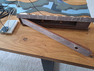
  Right at the heart of the Nikol-AI box there is a Useless machine  hidden inside a secret compartment that appears at the very end of the game. I tried long and hard to make a standard machine fit in the space available but in the end I had to make the whole box skinnier by about 9mm. The useless machine drops into the box from it's compartment so I actually had to move the batteries inside the machine to ensure that it drops without flipping over. The new location has the weight of the batteries spread evenly across the width but also at the top of the box so the drop helps it slide out towards the front of the compartment. Chris was suitably impressed with the reveal  to the point where he had to explain that it wasn't just tv trickery.

How to Flicker an LED

Image
In the last tutorial we covered how not to blink an LED , where I explained what was wrong with the most common blink example and showed a much more elegant solution. We now have an LED that switches between 'Off' and 'Blindingly Bright', there has to be another way that gives us more control over the LED, reduces the brightness (and therefore power consumption) and that could also give us a bit more 'character' for our lights. The answer is Pulse Width Modulation , or PWM for short. By switching the LED power on and off, imperceptibly quickly we can control the average amount of Voltage that is supplied to the LED, which in turn reduces the current and brightness of the LED. If we switch the power on and off faster than the LED can react, the LED will receive an average Voltage that is proportional to the ratio between on and off. If the LED is on for half the time and off for half the time it will receive half of the full voltage. It is possible to create the...